

 Technical Information Power And Control Cables Power Appendixes Fire Performance of Cable CABLE GLANDS
 Page CABLE GLANDS
|
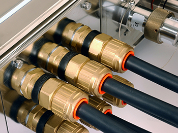
What is a Cable Gland? “A device designed to permit the entry of a cable into electrical equipment and which provides sealing and retention. It may also provide other functions such as earthing (or grounding), bonding, insulation, strain relief or a combination of these.” In addition to this a cable gland should maintain the overall integrity of the enclosure into which it is to be fitted . |
 |
|
How To Select The Correct Gland ? Cable Glands can be viewed as either: 1) Industrial or 2) Ex Hazardous Area . Ex Hazardous Area glands are further subdivided into: 2-1)Exd – Flameproof glands: meet both general requirements for hazardous areas plus the extra requirements for the flameproof standards and can therefore be used in both flameproof and increased safety applications. 2-2)Exe – Increased Safety Glands: meet only the general requirements for hazardous areas. Within the Exd category we must also consider whether the use of a barrier gland is appropriate… |
|
 |
 |
|
Barrier Glands vs. Elastomeric Seal Glands? A barrier gland is an Ex d cable gland incorporating a compound filled chamber sealing around the individual cores of the cable to maintain the Flameproof integrity of the equipment into which it has been fitted. A barrier gland must be used if it is thought that using a gland with elastomeric sealing will not maintain the Ex integrity of the flameproof equipment and also contain an explosion within the enclosure. There are several important questions that must be asked to determine whether or not a barrier gland is necessary: * Is the cable substantially round and effectively filled? * Is the size of the Exd enclosure greater than 2L in volume? * Is the installation to be in a zone 1 area? * Does the installation have an internal source of ignition? * Does the hazardous gas require IIC apparatus? |
|
 |
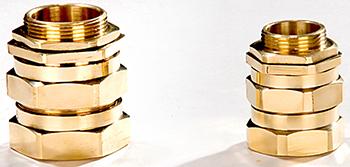 |
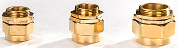
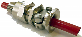
| BW Type Cable Glands | CW Type Cable Glands |
|
IEC 60079-14 (2007) , Part 14: Electrical installations design, selection and erection (Part 10.4.2) Selection of cable glands : The cable entry system shall comply with one of the following: a) cable glands in compliance with IEC 60079-1 and certified as part of the equipment when tested with a sample of the particular type of cable; b) where a cable, in compliance with 9.3.1(a) is substantially compact; a flameproof cable gland, in compliance with IEC 60079-1, may be utilized, providing this incorporates a sealing ring and is selected. c) mineral-insulated metal-sheathed cable with or without plastic outer covering with appropriate flameproof cable gland complying with IEC 60079-1; d) Flameproof sealing device (for example a sealing chamber) specified in the equipment documentation or complying with IEC 60079-1 and employing a cable gland appropriate to the cables used. The sealing device shall incorporate compound or other appropriate seals which permit stopping around individual cores. The sealing device shall be fitted at the point of entry of cables to the equipment; e) Flameproof cable gland, specified in the equipment documentation or complying with IEC 60079-1, incorporating compound filled seals or elastomeric seals that seal around the individual cores or other equivalent sealing arrangements; |
|
 |
 |
|
Industrial Cable Gland Specification : The current European standard for cable glands, EN 50262, was published on March 1st 1999. As a result, the BS 6121 series of British Standards for cable glands was withdrawn. It is important to understand that there has been a change in the basic methodology. The existing BS 6121, a physical dimensional standard, ensures a single and relatively high level of performance. EN 50262 provides a design framework that ensures a product meets the minimum requirements for safety. The most basic products designed to meet EN 50262 may fall short of meeting the users requirements. It is important to realise that although manufacturers will provide more information than before, but the user must now make more decisions regarding the suitability of the product for the application. BW glands are no longer classified as a gland within this new standard. General Issues : Once it has been decided which classification of gland you are going to use, there are issues that need to be considered that are applicable to ALL cable glands, thus maintaining the overall integrity of the installation: * The Type of Cable being used. * The Gland Size * The Entry Type/Thread Specification of the application * The Ingress Protection required * Material |
|
|
Selection procedure of Cable GLANDS : A- The Type of Cable: A-1) Unarmoured cables will require the outer sheath seal within the gland to not only provide ingress protection but also a degree of retention. A-2) Armoured cables require a gland that features a clamping mechanism to terminate the armour both mechanically and electrically. The gland will usually be required to provide ingress protection by sealing on the outer sheath and retention by clamping the armour. Typically, armoured cables feature an inner sheath that the gland may be required to seal on. B- Gland size : The entry thread (i.e. M20) is not, as often perceived the gland size but simply the entry thread size and specification. It is important to understand that selection of the correct gland size is based solely on the following cable dimensions: B-1) Outer Sheath Diameter ,and where applicable: B-2) Inner Sheath Diameter (Under Armour) B-3) Armour / Braid / Tape Thickness All Peppers Cable Gland data sheets have tables including ranges for each of the above measurements |
 |
|
C- Cable entry - Entry type and/or thread specification : If your installation has: Clearance holes – Need to be drilled in accordance with Standard BS EN 50262. A locknut will be required to fix the gland securely within a clearance hole. It is generally recommended that tapered threads should not be used with clearance holes. D- Threaded Entries : Glands can generally be supplied with a male thread to match the female enclosure thread. If this is not possible Thread Adaptors or Reducers can be used to match dissimilar threads. If the wall thickness will permit, the use of a locknut will provide additional security. E- Ingress Protection : It is essential when selecting cable glands and or accessories to ensure that the products will maintain the IP rating of the equipment and the integrity of the installation. IP codes are based on the IEC Standard 60529, degrees of protection provided by enclosures. In most cases standard cable glands will maintain Ingress Protection of the equipment into which they are installed to. Please note that clearance holes must be drilled in accordance with EN 50262 table 1 and any gland without a integral “O” ring must have a suitable IP washer fitted in order to maintain greater than IP54. F- A Common Misconception: “The higher the IP number the better IP Protection offered.” Truth: The different IP numbers refer to different ingress tests G- Material : The selected gland should be manufactured from a material that is suitable for the surrounding environment. It is essential that the material of the gland you select will not react adversely with the material of the enclosure into which it is installed. As a particular example it should be noted that Brass, the standard material for metallic glands, can react adversely with Aluminium, if moisture becomes present bi-metallic corrosion may occur. When using brass glands sea water, H2S, SO2 and ammonia are the most problematic environments. Nickel, tin or zinc plating can be applied to brass to both minimize the potential for bi-metallic corrosion and provide a degree of protection from the surrounding environment. |
|
|
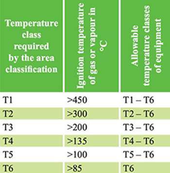
Other Issues for Selection of Cable GLANDS : Operating Temperatures : The metallic body of the gland is generally suitable for operating temperatures that glands are used at, meaning that the seal material and/or IP interface is generally the limiting factor. Neoprene seals are suitable from –20°C to +85°C and can be used as low as –60°C but the structure of the material may be affected adversely and this could result in material breakdown. Meaning that for lower temperatures silicone seals should be considered. Silicone seals are suitable for extended operating temperatures of –60°C to +180°C (–60°C to +135°C for barrier glands) and should be used for low temperature applications as the seal performance can be maintained throughout the lifetime of the installation. To ensure that the surface temperature of the equipment will not ignite gases or vapours in the surrounding atmosphere, the equipment will specify a ‘T’ rating based on the maximum surface temperature that can occur during its operation. As cable glands are passive and do not generate heat they have no effect on the ‘T’ rating of the equipment and does not need to be considered when selecting a gland. |
 |
 |
|
| New delevopments in Cable Glands : | |
 |
 |
|
Connect two Ex d – Flameproof enclosures : Traditional practice has been to use a compound barrier gland mounted at the entry of both enclosures with a length of cable or conduit . New barrier glands can now be installed directly between two Ex d enclosures that is more cost effective solution. |
Breather Drain : Breather Drain provides a method of effectively draining any moisture within an enclosure whilst allowing the air inside to breathe with the surrounding atmosphere . |